 Kia Rio: ESC Operation Mode
| ESC Hydraulic System Diagram |
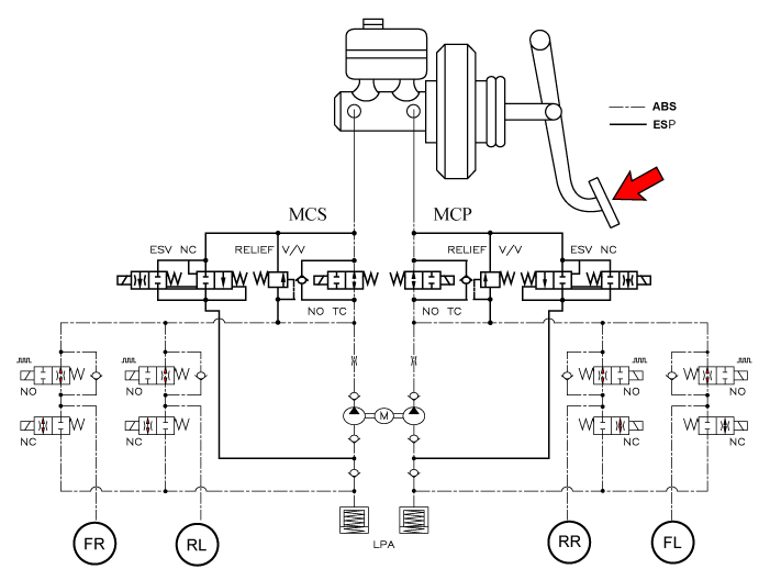
| 1. |
ESC Non-operation : Normal braking.
|
| 2. |
ESC operation
|
||
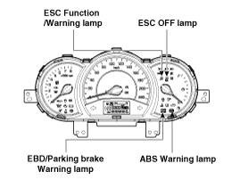
ABS Warning Lamp module
The active ABS warning lamp module indicates the self-test and failure
status of the ABS. The ABS warning lamp shall be on:
| - |
During the initialization phase after IGN ON. (continuously 3
seconds).
|
| - |
In the event of inhibition of ABS functions by failure.
|
| - |
During diagnostic mode.
|
| - |
When the ECU Connector is separated from ECU.
|
| - |
Cluster lamp is ON when communication is impossible with CAN module.
|
EBD/Parking Brake Warning Lamp Module
The active EBD warning lamp module indicates the self-test and failure
status of the EBD. However, in case the Parking Brake Switch is turned on, the
EBD warning lamp is always turned on regardless of EBD functions. The EBD warning
lamp shall be on:
| - |
During the initialization phase after IGN ON. (continuously 3
seconds).
|
| - |
When the Parking Brake Switch is ON or brake fluid level is low.
|
| - |
When the EBD function is out of order .
|
| - |
During diagnostic mode.
|
| - |
When the ECU Connector is separated from ECU.
|
| - |
Cluster lamp is ON when communication is impossible with CAN module.
|
ESC function/warning lamp
The ESC function/warning lamp indicates the self-test and failure status
of the ESC.
The ESC function/warning lamp is turned on under the following conditions
:
| - |
During the initialization phase after IGN ON. (continuously 3
seconds).
|
| - |
When the ESC function is inhibited by system failure.
|
| - |
When the ESC control is operating. (Blinking - 2Hz)
|
| - |
During diagnostic mode.(Except standard mode)
|
| - |
Cluster lamp is ON when communication is impossible with CAN module.
|
ESC Off Lamp
The ESC Off lamp indicates the self-test and operating status of the ESC.
The ESC Off lamp operates under the following conditions :
| - |
During the initialization mode after IGN ON. (continuously 3 seconds).
|
| - |
ESC Off lamp is On when driver input the ESC Off switch.
|
ESC On/Off Switch
The ESC On/Off Switch shall be used to toggle the ESC function between
On/Off states based upon driver input.
The On/Off switch shall be a normally open, momentary contact switch.
Closed contacts switch the circuit to ignition.
Initial status of the ESC function is on and switch toggle the state.
Electronic Stability Control (ESC) recognizes critical driving conditions,
such as panic reactions in dangerous situations, and stabilizes the vehicle
by wheel-individual braking and engine c ...
Circuit Diagram - ESC (1)
Circuit Diagram - ESC (2)
Circuit Diagram - ESC (3)
Circuit Diagram - ESC (4)
ESC connector input/output
Connector Terminal
Specifi ...
 Description of ESC
Electronic Stability Control (ESC) recognizes critical driving conditions,
such as panic reactions in dangerous situations, and stabilizes the vehicle
by wheel-individual braking and engine c ...
 Schematic Diagrams
Circuit Diagram - ESC (1)
Circuit Diagram - ESC (2)
Circuit Diagram - ESC (3)
Circuit Diagram - ESC (4)
ESC connector input/output
Connector Terminal
Specifi ...
See also:
Oil Pump Unit (OPU) Inspection
OPU Problem Inspection Procedure
1.
TEST OPU GROUND CIRCUIT: Measure resistance between OPU and chassis
ground using the backside of OPU harness connector ...
Specification
Engine
T/M
Joint type
Max. permissible angle
Outer
Inner
Outer
Inner
Gasoline 1.6
MT, AT
BJ#82
TJ#82
...
Specification
Item
Bulb Watt (W)
Bulb Type
Front
Head lamp (High)
60/55
H1
Head lamp (Low)
60/55
H7
Position lmap
...
Copyright © www.kirmanual.com 2014-2024