 Kia Rio: Inhibitor Switch Installation
| 1. |
Check that the shift lever is placed in the "N" position
|
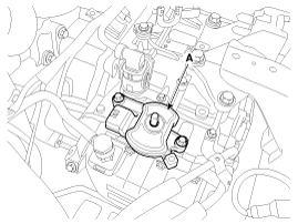
| 2. |
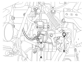
Install the inhibitor switch (A).
|

| 3. |
Install the manual control lever (A).
|
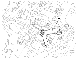
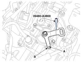
| 4. |
Align the hole (A) in the manual control lever with the "N" position
hole (B) of the inhibitor switch and then insert the SST inhibitor switch
guide pin (09480-A3800).
|
| 5. |
Tighten the nut (A) and bolts (B) with the specified torque.
|
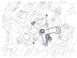
| 6. |
Remove the SST (09480-A3800) from the hole.
|
| 7. |
Connect the inhibitor switch connector (A).
|
| 8. |
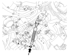
Install the shift cable by tightening nut (B).
|
| 9. |
Push the shift cable to the arrow "F" to eliminate free play and
then tighten the nut (A) with the specified torque.
|
| 10. |
Install the battery and battery tray.
(Refer to Engine Electrical System - "Battery")
|
| 11. |
Install the air cleaner assembly.
(Refer to Engine Mechanical System - "Air cleaner")
|
 Inhibitor Switch Removal
1.
Place the shift lever into the "N" position.
2.
Remove the air cleaner assembly.
(1)
Remove t ...
 Shift Lever Components
1. Shift lever knob
2. Shift lever assembly
3. Control cable
4. Shift lock cable assembly
5. Retainer
6. Brake pedal assembly
...
See also:
Removal
1.
Remove the front wheel & tire.
Tightening torque:
88.3 ~ 107.9 N.m (9.0 ~ 11.0 kgf.m, 65.1 ~79.6 lb-ft)
...
SS-A Solenoid Valve(ON/OFF) Removal
1.
Remove the battery and the battery tray.
(Refer to "Charging system" in EE group.)
2.
Remove the under cover (A).
...
Meaning Of Symbols
There are five primary symbols used to complement illustrations. These
symbols indicate the part to apply such materials during service.
Symbol
Meaning
...
Categories
- Kia Rio Manuals Home
- Kia Rio UB 2012-2017 Owners Manual
- Kia Rio UB 2012-2017 Service Manual
- Downloads
Copyright © www.kirmanual.com 2014-2025