 Kia Rio: Front Wheel Alignment
When using a commercially available computerized wheel alignment
equipment to inspect the front wheel alignment, always position the
vehicle on a level surface with the front wheels facing straight ahead.
Prior to inspection, make sure that the front suspension and steering
system are in normal operating condition and that the tires are inflated
to the specified pressure.
|

Toe
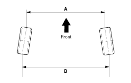
B - A > 0: Toe in (+)
B - A < 0: Toe out (-)
|
Toe Adjustment
| 1. |
Loosen the tie rod end lock nut.
|
| 2. |
Remove the bellows clip to prevent the bellows from being twisted.
|
| 3. |
Adjust the toe by screwing or unscrewing the tie rod. Toe adjustment
should be made by turning the right and left tie rods by the same amount.
|
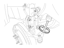
| 4. |
When completing the toe adjustment, install the bellows clip and
tighten the tie rod end lock nut to specified torque.
|
| 5. |
Compensate the steering angle sensor after adjusting the wheel
alignment.
(Refer to Steering System - "Steering Column-Shaft")
|
Camber and Caster
Camber and Caster are pre-set at the factory, so they do not need to be
adjusted. If the camber and caster are not within the standard value, replace
or repair the damaged parts and then inspect again.
Camber angle : -0.5° ±
0.5°
|
Caster angle : 4.1° ± 0.5°
|
 Tires/Wheels
...
 Rear Wheel Alignment
When using a commercially available computerized wheel alignment
equipment to inspect the rear wheel alignment, always p ...
See also:
Component Replacement After Deployment
Before doing any SRS repairs, use the GDS Pro to check for DTCs.
Refer to the Diagnostic Trouble Code list for repairing ...
Multimedia Jack Troubleshooting
Symptom
Suspected area
Repairment
Pressing power switch does not turn on system
Radio receiver power source circuit
R-1
LCD module
R ...
Categories
- Kia Rio Manuals Home
- Kia Rio UB 2012-2017 Owners Manual
- Kia Rio UB 2012-2017 Service Manual
- Downloads
Copyright © www.kirmanual.com 2014-2025